This is part 2 about my MP3 player project. If you missed part 1, you’ll probably want to start there.
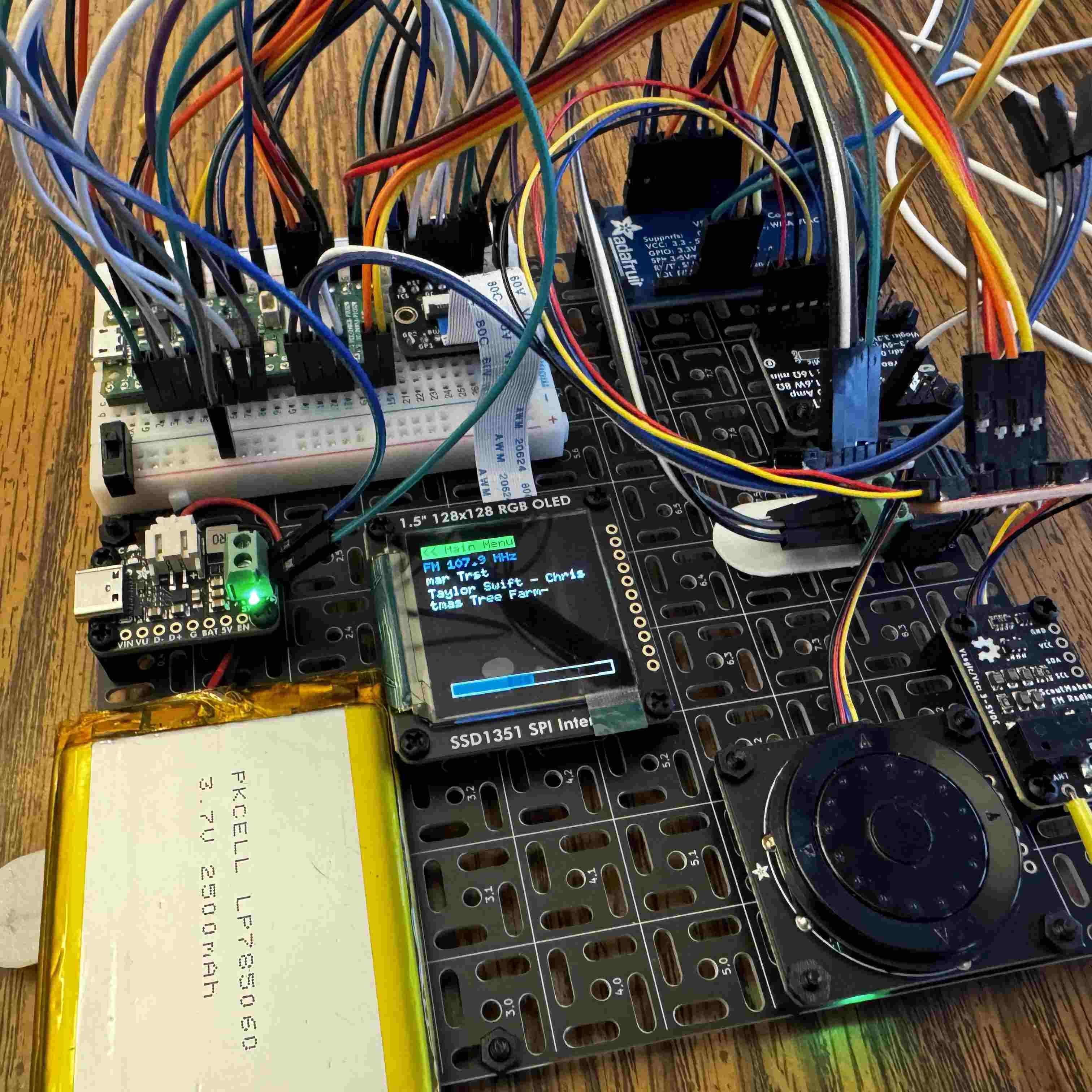
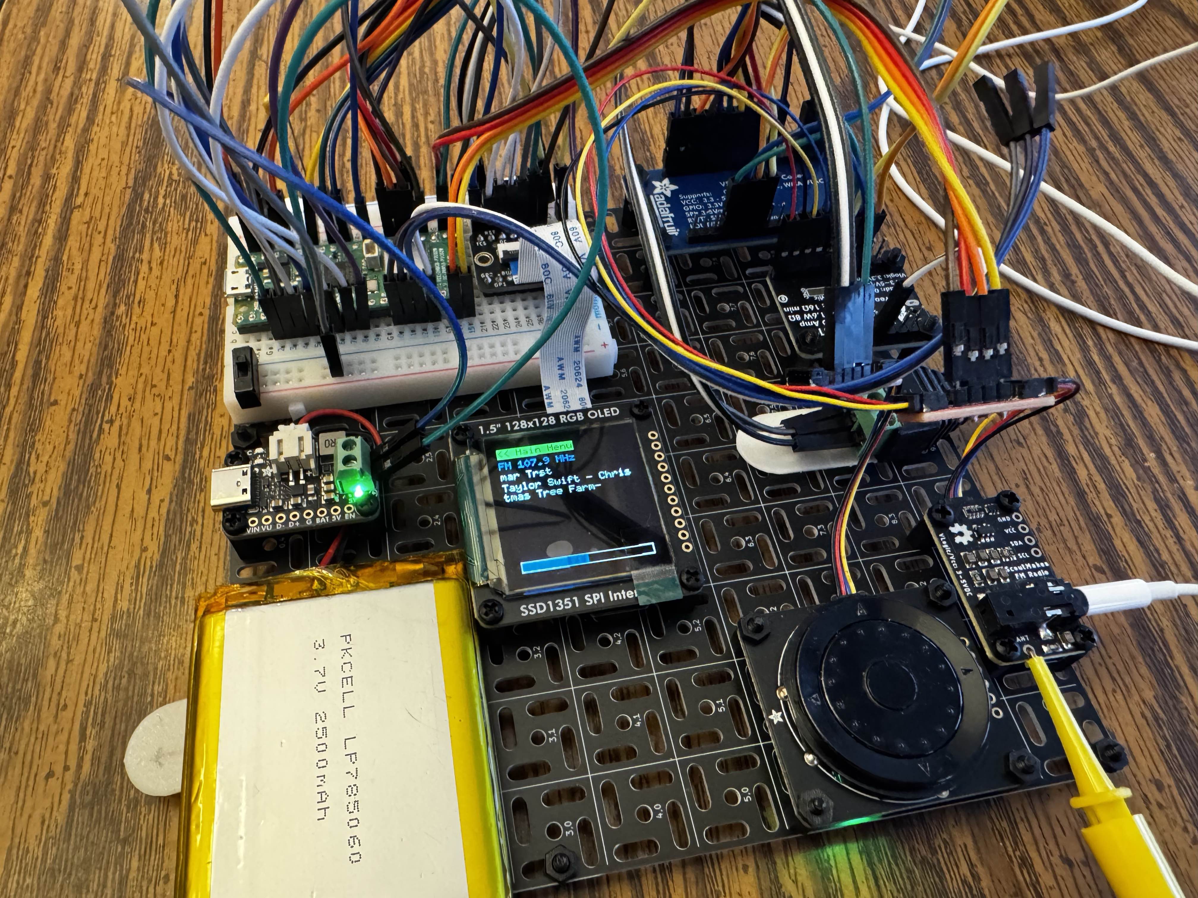
Recapping, I’m trying to build an MP3 Player, that also includes FM Radio, GPS, and maybe some games.
Getting the Magnetometer Calibrated & Working
I got the magnetometer working. Fairly easy. Read and write the upper/lower halves of the readings from 6 registers, and you get x, y, and z readings.
The new thing I learned about in my research - is how and why this needs to be calibrated. The levels the magnetometer read actually differ a bit, and I imagine, place to place. The naive heading is computed by running the function below - see, we do use trig functions in the real world!
But, these x/y readings can be slightly skewed, and if you just compute the heading from the raw readings, you’ll get a compass bearing that never reaches 360, or 0. The “hard-iron” calibration I’m doing is very simple. Record the , , and . Then, we calibrate the x/y using them.
Then, change the heading, to the following:
Once you spin the compass around a full circle, it will correctly orient north!
I published my driver here, but it’s neither cleaned up, nor suitable for purposes beyond these.
The tlv320dac3100
I found a library for this that I thought would be helpful. But unfortunately, there’s no instructions or example code with it. So - you end up trying to reverse engineer the library to implement the instructions to initialize (which are quite complicated). I did this - and missed something with the library. I ended up forking it so I could send commands more-or-less like the datasheet does on page 49.
// A ***SUBSET*** of the commands - there's about 25 of them needed to initialize the DAC
match i2s_dac_tlv320.write_multiple_regs(&[
    // (b) Power up DAC channels and set digital gain
    // power up dac left and right channels (soft step enabled)
    (0, 0x3F, 0xD4),
    // DAC left gain = -22db
    (0, 0x41, 0xD4),
    // DAC Right gain = -22db
    (0, 0x42, 0xD4),
    // (c) Unmute digital volume control
    // unmute DAC left and right channels
    (0, 0x40, 0x00),
]) {
    Ok(_) => {
        info!("TLV320 DAC Channels Powered Up and Digital Gain Set");
    }
    Err(e) => {
        log::info!(
            "TLV320 DAC Channels Power Up and Digital Gain Set Error: {:?}",
            e
        );
    }
}
With this, I was able to get the I2s square wave to work.
MP3 Adventure
This part, was much more interesting, and frustrating. I tried to integrate nanomp3 in the place of the embassy square wave demo.
Trying CPU Decoding
For a test file, I sliced off the first 10 seconds of YTCracker’s “Bitcoin Baron”, and encoded it as a 48khz 128kpbs mp3. FAR too high quality for decoding with the pico it seemed. When you played it - you could hear all kinds of artifacts, with faint echoes of the music in the background, slowed down.
The way the DMA system I had set up based on the demo, uses a front/back buffer and swaps them. The PIO peripheral in the PI was set to clock out the front buffer data over a GPIO port for the DAC to consume and play. BUT - if you’re unable to decode enough data and fill the back buffer in the time it takes to DMA out your front buffer, it ends up missing samples. And then it sounds really bad.
I did some work and severely down-sampled the mp3 to 24khz, and something like 32k bitrate, to see if it’d work. It sounded better but the mp3 distortion took over and even with that, the artifacts of the buffering still missing every so often, sound bad.
Not the best music player experience.
Pivoting!
So, I’m pivoting my MP3 approach a little. I’m going to try some alternative libraries other than nanomp3 but I suspect the RP2350 is still a little too slow. I could probably do wav files, but I’m not really a fan of the whole ‘transcode my whole library’ thing.
As a result - my new approach is to use this mp3 codec breakout instead. It still should be able to be configured to write I2s - so I can use the fancy dac / mixer for volume control across fm radio and that. But - it looks like I might be able to either add voice memos since it has some inputs for that. We’ll see.
With this approach, the CPU should be much more freed up for networking, interface drawing, etc.
With this, I was able to get files to play of the SD card. BUT - the screen seems to be changing some settings on the SPI bus and the sd card won’t work alongside it yet. If I disable the screen entirely in the codebase, I can play my test mp3 file off of the SD card!
I’m still iterating on this. With the new codec - it works, but I need to resolve those issues with the screen & sd card not playing nice on SPI bus 0. The driver I found for the VS1035 works, but it doesn’t use the SPIDevice trait, and instead wants to own the entire SPI bus. I’m trying to modify this library currently so that I can use the same SPI bus for SD card and for the audio codec. Something the video driver does when writing the image, makes the SD card stop working once we run a display.flush().
In my revised dev setup - I have removed the GPS and magnetometer temporarily - I was finding that having those and the rotary encoder on the same bus sometimes caused the encoder to not initialize. I have acquired an I2C multiplexer - but I need to integrate that into the codebase.
Part of me wants to ditch most of the external peripherals, gps, fm radio, etc- and just go straight MP3 to simplify things later on when trying to build a case for this. But - that doesn’t solve my SPI bus troubles, as all those peripherals are I2C.
The praises of the Pico Probe
I’m very glad that I bought one of these - if you have a Pico with the debug port pre-soldered, it’s a breeze to connect (potentially after upgrading the probe firmware), probe-rs is able to flash and debug over the port. And when things panic!() - it prints why.