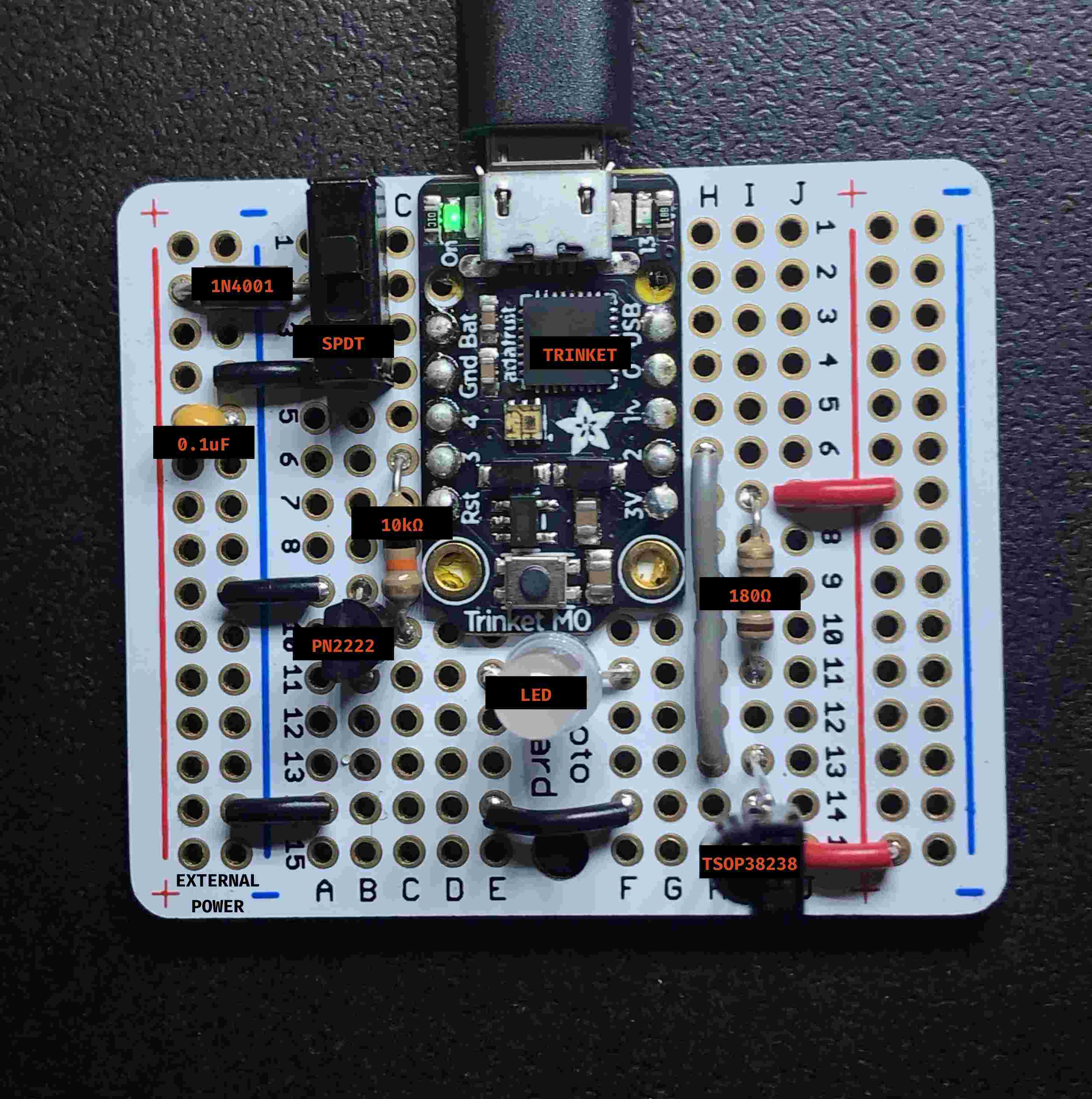

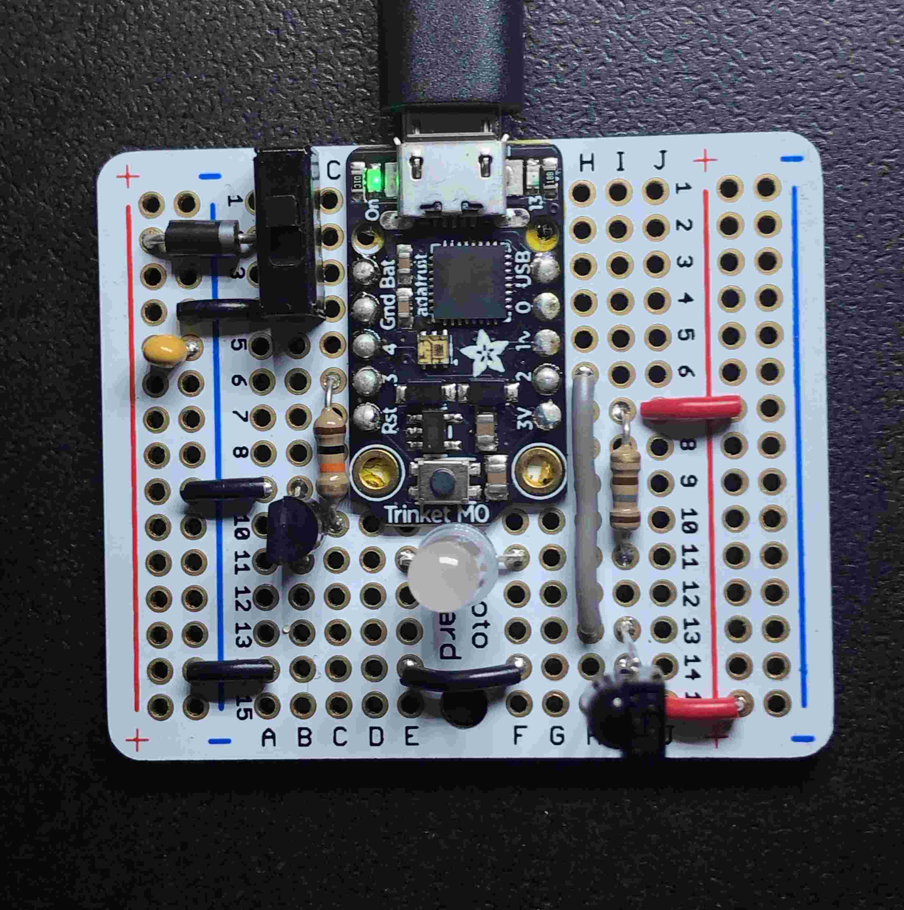
This project uses CircuitPython & Adafruit’s trinket m0 for decoding the IR signals, Since the LED’s supposed to draw about 20mA, and the pads on the Trinket’s documentation specifies a max of 7mA for each pad, we use an NPN transistor to toggle the LED. It’s programmed with CircuitPython, and code can be found here.
Parts List
- Trinket M0 (1x)
- PN2222 Transistor (NPN) (1x) datasheet
- TSOP38238 IR Sensor (1x)
- Perma-Proto Quarter-sized PCB (1x) datasheet
- 10kΩ resistor (1x)
- 180Ω resistor (1x)
- Warm White 5mm Diffused Candle Flicker LED
- 1N4001 diode (optional) (1x) datasheet
- SPDT slide switch (optional) (1x)
- 0.1uF ceramic capacitor (#104) (optional) (1x)
Extra Features
- Alternate power supply can be added from ~3.3-6V on the left rail. A tiny ceramic capacitor is used for smoothing voltage spikes, and the input is switchable to allow for non-IR operation.
- The trinket m0 has built-in usb for programming
- It can be adapted to recieve codes from most IR remotes to integrate with existing lighting.
Notes
- Attaching the trinket is done by centering it on the pads on the protoboard, and surface soldering it through the holes.
- The 10kΩ resistor is connected from digital out #3 to the base of the NPN transistor.
- The 180Ω resistor connects the +3V source to the positive terminal of the LED.
- The LED is then connected to the collector of the NPN transistor.
- The Emitter of the NPN transistor is then grounded.
- The IR Sensor’s OUT pin is connected to digital in #2 and decoded in software.
- The IR Sensor’s Vs and GND pins are connected to +3V and ground.
Programming
Programming is done by replacing the main.py on the circuitpython drive with the code here. We must also copy the adafruit_irremote and adafruit_dotstar libraries into libraries folder.
Schematic

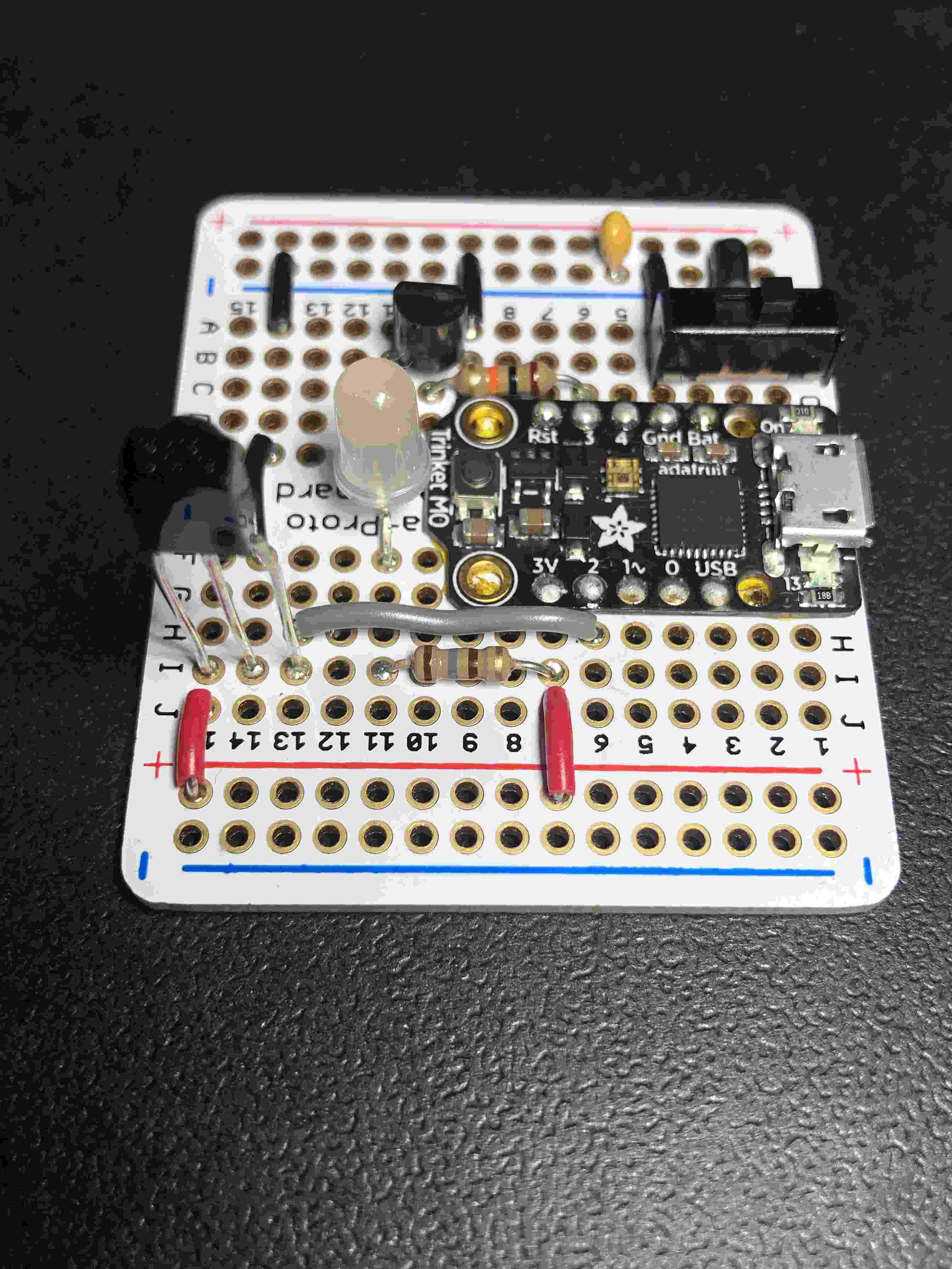
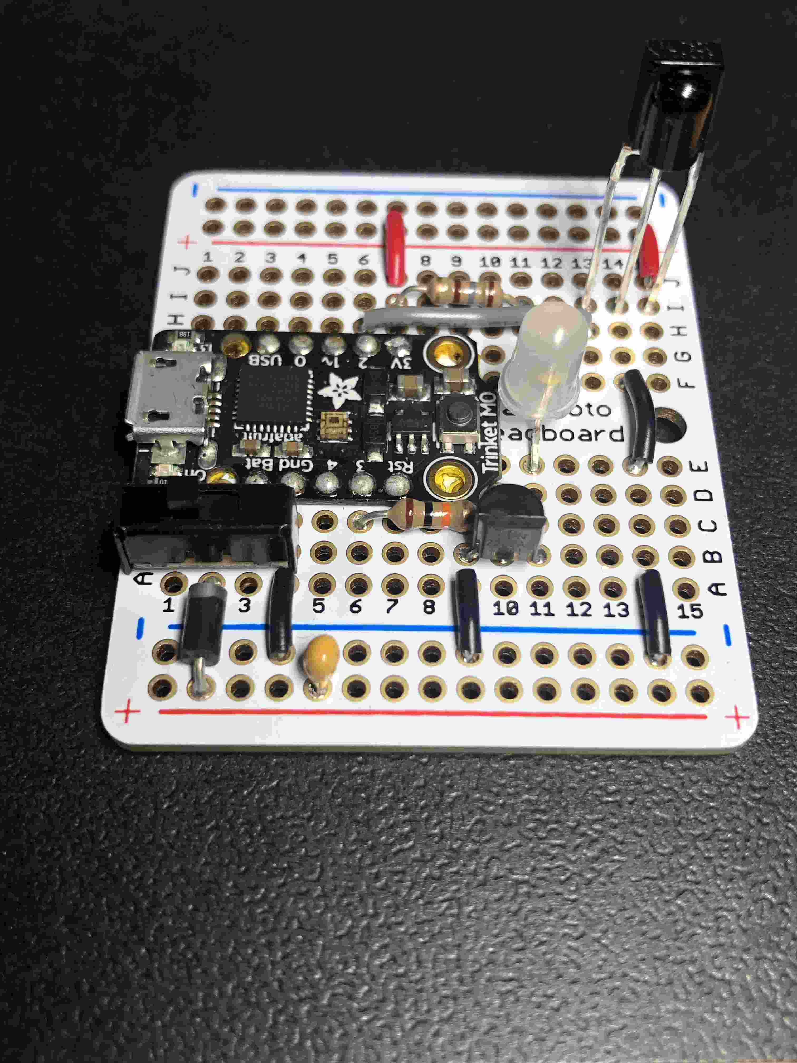
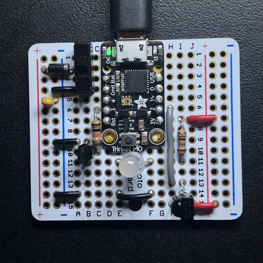
Additional Images